Descrizione generale – General description
Voglio descrivere in poche parole il sistema per controllare da remoto una camera Z-Cam (ma in teoria è adattabile a tutte le camere con supporto LANC), progettato per essere usato insieme al controllo remoto di un drone o , come nel mio caso, di una cablecam.
Uno degli aspetti fondamentali di questo progetto è l’utilizzo della stessa frequenza usata per comandare la cablecam e il gimbal, eliminando quindi il problema di interferenze. Il sistema è molto semplice, ed è composto da pochi ma selezionati componenti.
I want to describe in a few words my remote control for Z-Cam camera (but adaptable to all cameras with LANC support), designed to be used together with the drone or (as in my case) cablecam remote control.
One of the fundamental aspects of this project is the use of the same frequency used to control the cablecam and the gimbal, thus eliminating every interference problems. The system is very simple, and need it only a few but selected components.
L’idea è quella di dare ad ogni evento di controllo della camera un codice, che viene trasmesso al ricevente tramite la codifica in valori PWM di due canali liberi sul sistema RC di controllo della cablecam /drone. Dato che i canali PWM trasmettono degli impulsi a durata variabile tra 1000 e 2000 ms, con lo zero posto a 1500 ms, per evitare possibili errori vengono trasmessi 4 bit su un canale (16 valori) e altri 4 bit sul secondo canale. In questo modo è possibile avere 256 codici trasmessi, che sono abbondantemente sopra al numero di quelli necessari.
The idea is to give each camera control event a code, which is transmitted to the receiver by coding in two free channels in PWM values on the cablecam / drone RC control system. Since PWM channels transmit pulses of variable duration between 1000 and 2000 ms, with the zero set at 1500 ms, to avoid possible errors, 4 bits are transmitted on one channel (16 values) and another 4 bits on the second channel. In this way it is possible to have 256 codes transmitted, which are a lotabove the number of those needed.
Touch Screen
il sistema si compone di tre elementi principali: un touch screen con tutti i comandi che è possibile trasmettere alla camera, che per ora ho sostituito con uno smartphone e una app da collegare tramite bluetooth. In seguito (sono in attesa della fornitura), la app potrà essere sostituita o affiancata da un lcd touch dedicato.
It consists of three main elements: a touch screen with all the commands that can be transmitted to the room, which for now I have replaced with a smartphone and an app to be connected via bluetooth. Later (they are awaiting supply), the app can be replaced or supported by a dedicated touch LCD.
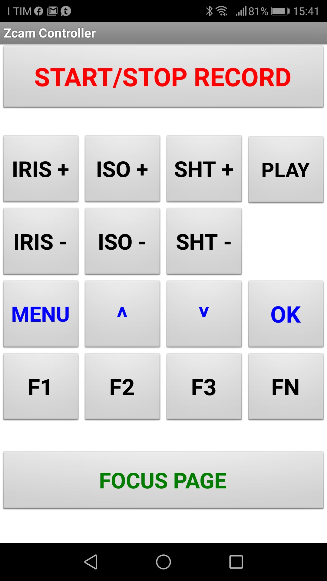
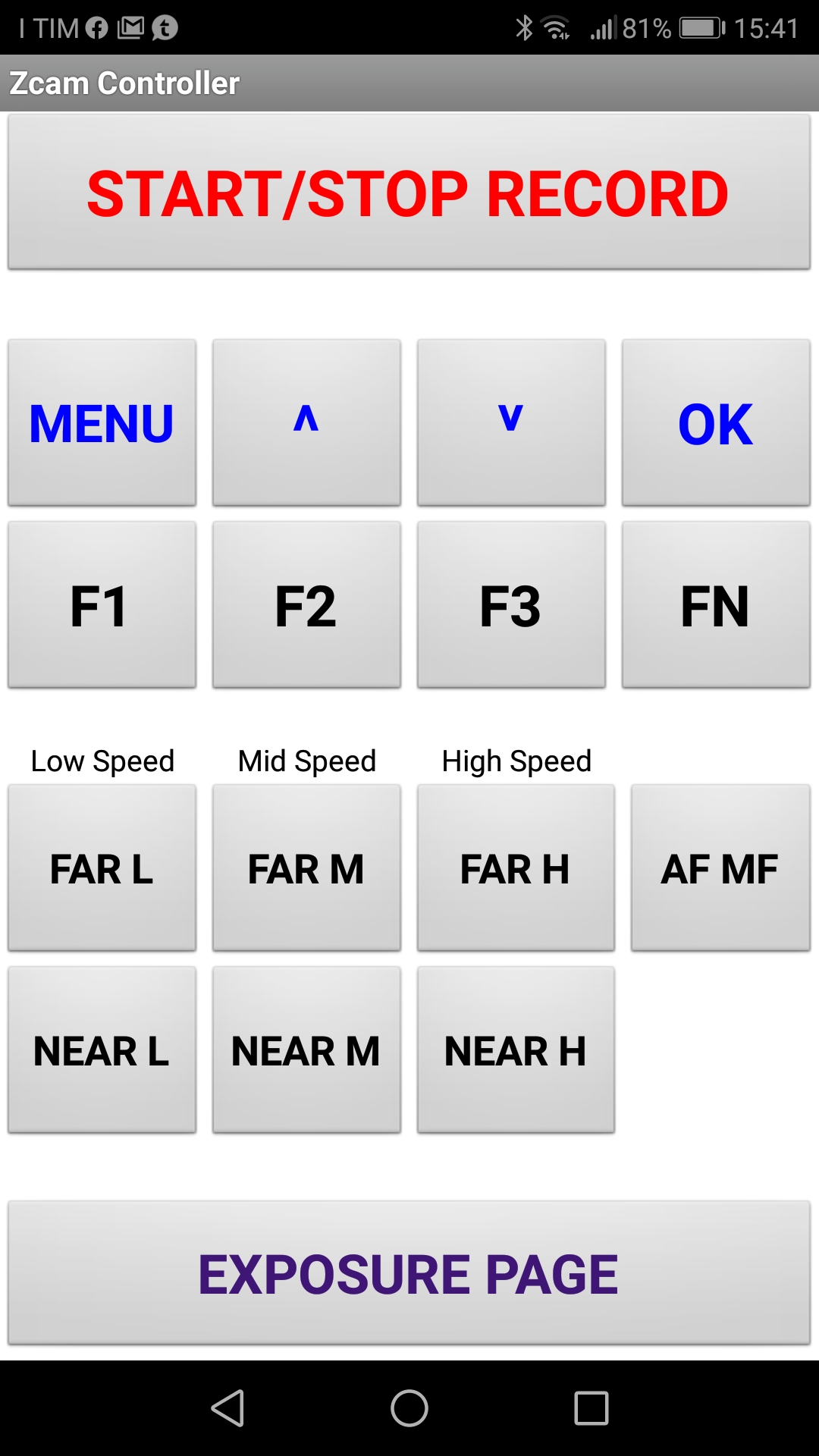
Queste sopra sono le due schermate che ho creato per i comandi. Sono divise in due categorie principali, l’esposizione e i fuochi (pensando al fatto che i fuochi possono essere gestiti solo su ottiche motorizzate). La parte con il menù e le funzioni è visibile in entrambe le pagine, come pure il tasto START/STOP record. Quest’ultimo, a differenza degli altri, richiede una pressione lunga perchè avevo notato che usandolo in modo tradizionale bastava sfiorare il tasto per fare partire o stoppare il rec. Così ho modificato la reazione di quel tasto per ragioni di sicurezza.
These above are the two screens I created for the commands. They are splitted into two main categories, exposure and focus (thinking of the fact that focus can only be managed on motor optics). The part with the menu and functions is visible on both pages, as well as the START / STOP record button. The latter, unlike the others buttons, requires a long press because I had noticed that using it in the traditional way it’s enaugh to touch the button to start or stop the rec. So I changed the reaction of that button for safety reasons.
Al momento, ho realizzato la app usando un sistema molto semplice che si chiama MIT App Inventor, una piattaforma online studiata per l’educational ma che permette di creare app perfettamente funzionanti.
At the moment, I made the app using a very simple system called MIT App Inventor, an online platform designed for education but which allows you to create fully functional apps.
Encoder Comandi e generatore PPM – Command encoder and PPM generator
Il secondo elemento, che è possibile vedere sotto nella fase di test, è composto da un microcontroller TEENSY 3.2, e da un convertitore bluetooth/seriale che mi ha permesso di fare i test con la app su smartphone. Dato che la scheda TEENSY dispone di 3 seriali, sarà possibile avere il touch screen e contemporaneamente il controllo da smartphone se qualcuno lo desidera. Dato che il controllo smartphone avviene tramite bluetooth, la distanza tra lo smartphone e la stazione trasmittente non può essere troppo elevata. Tuttavia la camera potrà essere a centinaia di metri senza problemi. La scelta di questo microcontroller è dovuta al fatto che oltre a disporre di 3 seriali ha una libreria per generare segnali PPM con elevata precisione. nella maggior parte dei casi, ad esempio se si usa solo il touch screen, un modulo arduino nano è sufficiente. Peraltro è possibile emulare le seriali sui pin se fosse necessario. Ho preferito le TEENSY perchè più veloci e ne avevo due in un cassetto…
The second element, which you can see below in the test stage, is composed of a TEENSY 3.2 microcontroller, and by a bluetooth / serial converter that allowed me to test with the app on a smartphone. Since the TEENSY card has 3 serial ports, it will be possible to have the touch screen and control from a smartphone at the same time if someone wishes. Since smartphone control is via bluetooth, the distance between the smartphone and the transmitting station cannot be too great. However, the distance from the Camera can be hundreds of meters away without problems. The choice of this microcontroller is due to the fact that in addition to having 3 serial lines, it has a library for generating PPM signals with high precision. in most cases, for example if you only use the touch screen, an arduino nano module is enaugh. Moreover, it is possible to emulate the serial numbers on the pins if necessary. I preferred the TEENSY because faster and I had two in a drawer …
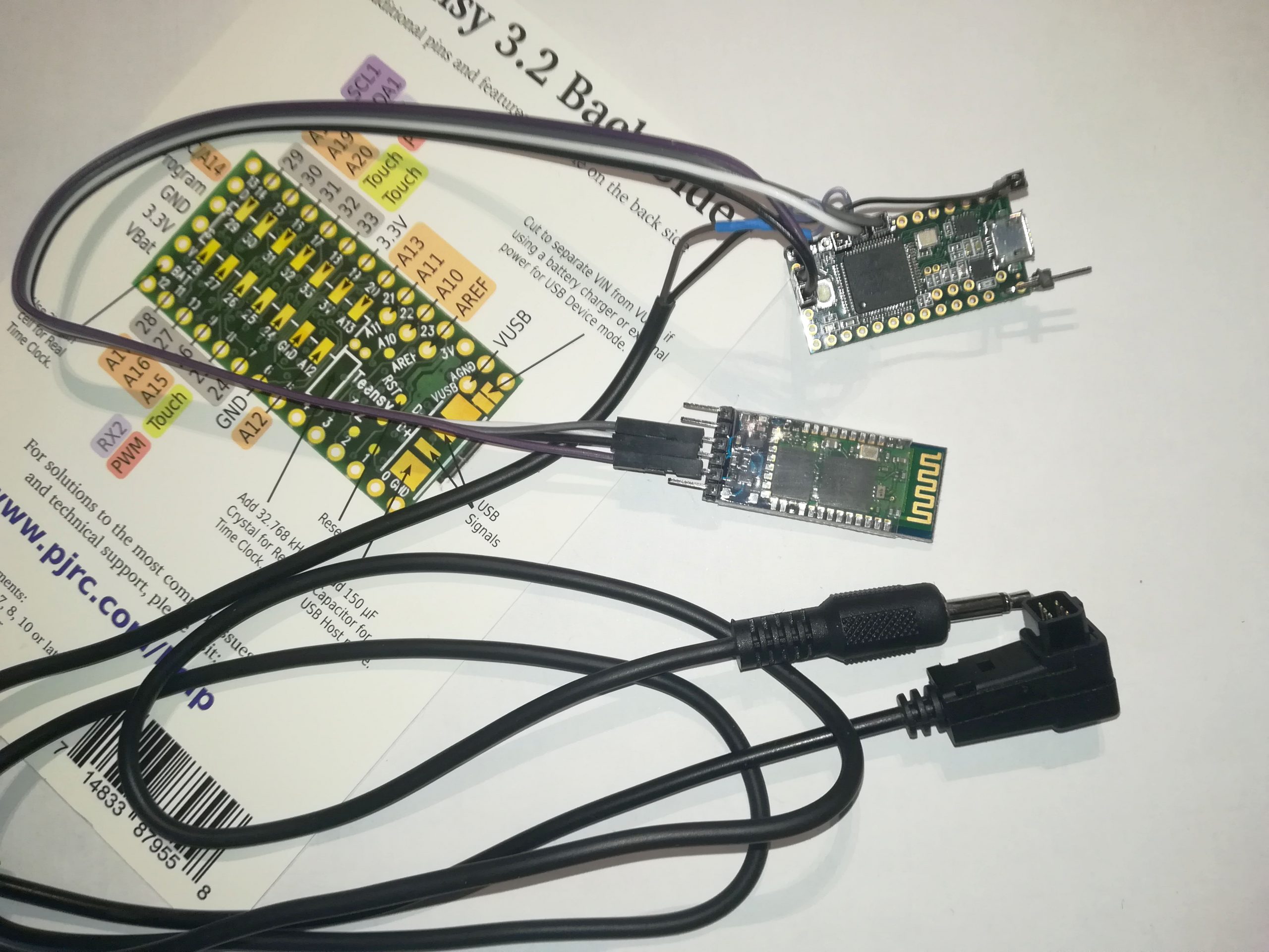
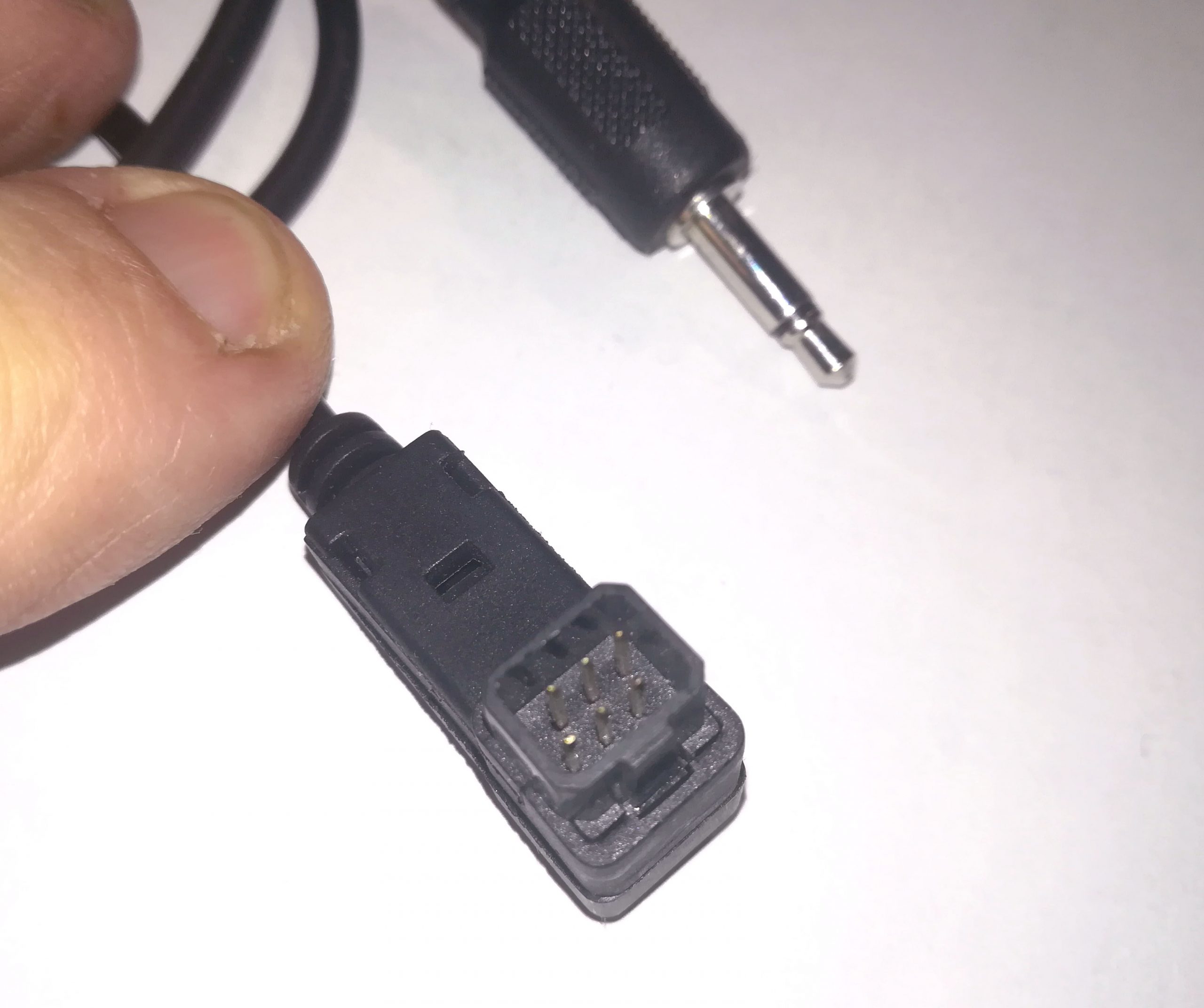
Nell’immagine sopra è possibile vedere la scheda TEENSY collegata al modulo bluetooth, e al cavo che trasmette il segnale PPM al trasmettirore RC. In basso si vedono i due connettori che possono essere usati a questo scopo, un normale jack o il connettore FUTABA. Io ho usato il jack, ma a seconda del trasmettitore RC è possibile usare l’uno o l’altro sistema.
In the above image you can see the TEENSY card connected to the bluetooth module, and the cable that transmits the PPM signal to the RC transmitter. Below in the image are the two connectors that can be used for this purpose, a normal jack or the FUTABA connector. I used the jack, but depending on the RC transmitter it is possible to use one or the other system.
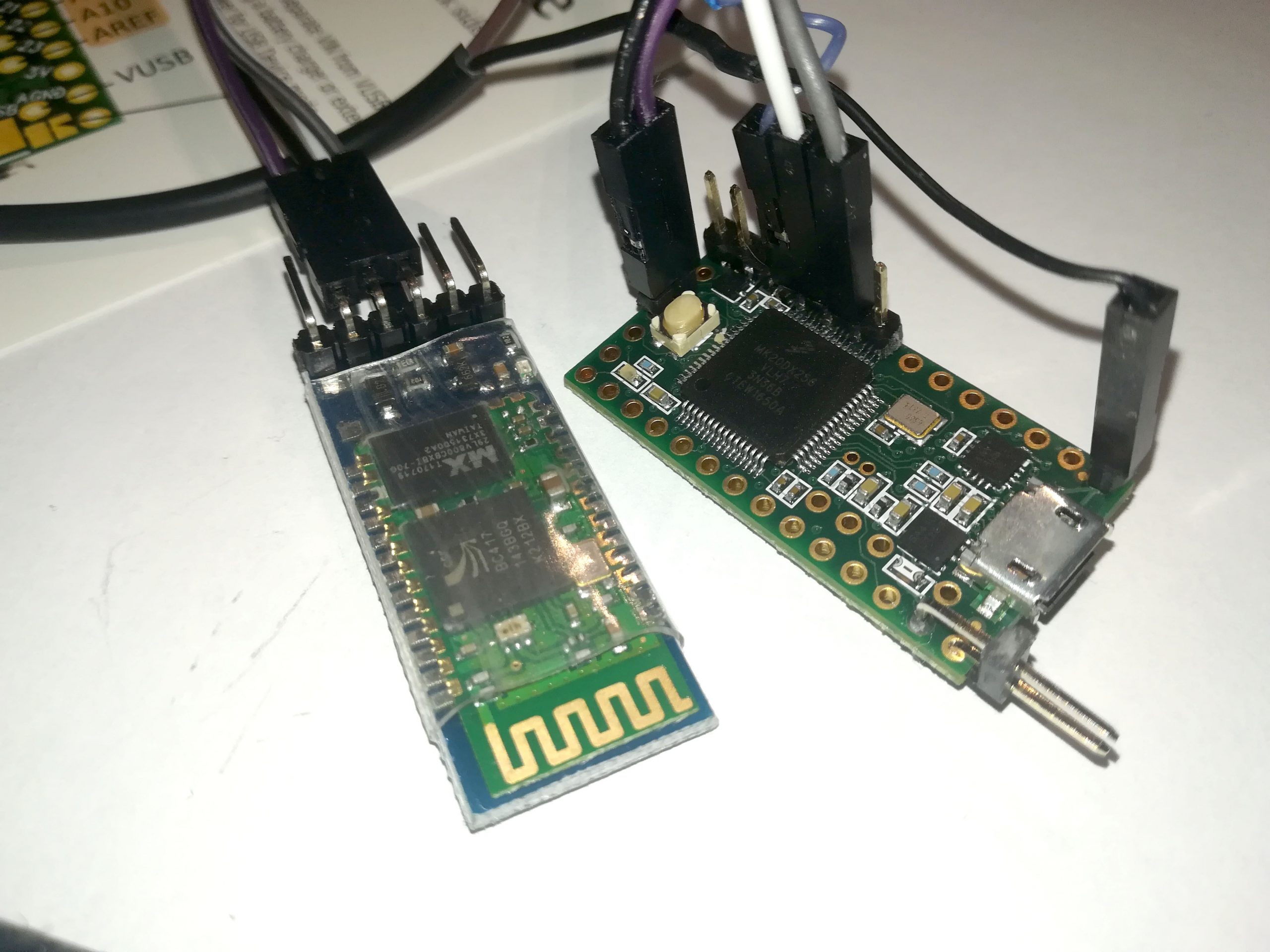
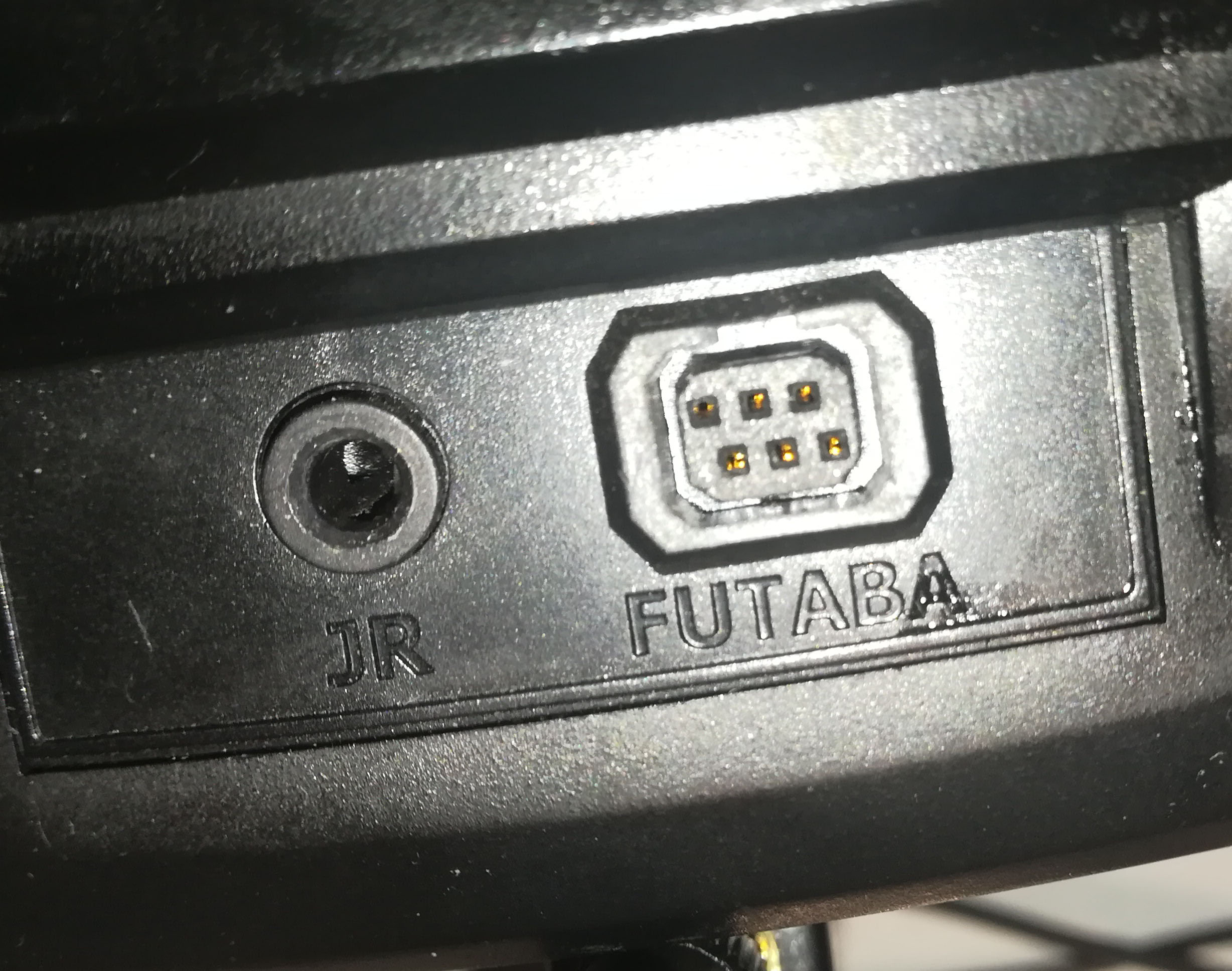
Sopra, due dettagli della scheda e dei connettori.
Above, two details of the card and connectors.
Impostazione trasmettitore RC – RC transmitter setting
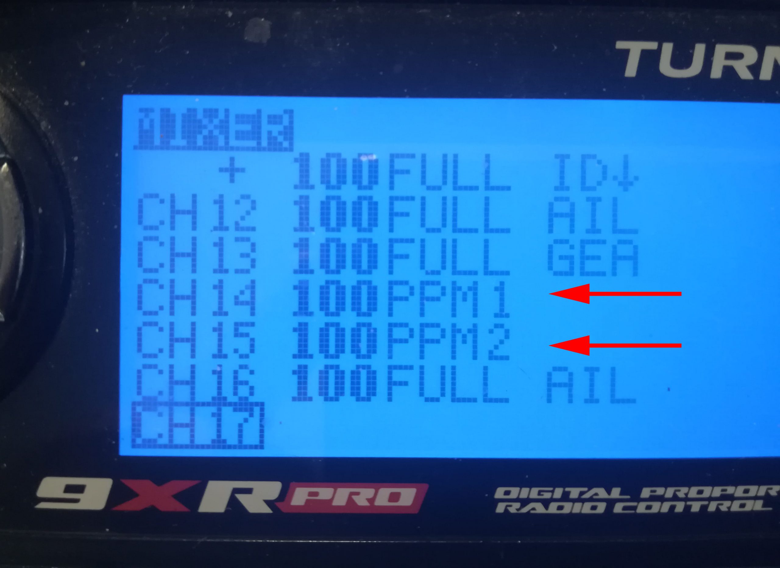
Per poter trasmettere alla stazione ricevente i comandi, ho utilizzato come descritto sopra la porta Trainer del mio trasmettitore RC. nell’immagine sotto si vedono i connettori dove colelgare il cavo della uscita PPM dal microcontroller TEENSY.
In order to transmit the commands to the receiving station, I used the Trainer port of my RC transmitter as described above. in the image below you can see the connectors where to connect the PPM output cable from the TEENSY microcontroller.
Questa possibilità è presente sul 99% delle radio RC in commercio. Quando la porta non è usata come Trainer vero e proprio, esiste la possibilità di utilizzare i PPM in ingresso per estendere le possibilità della radio o per altre applicazioni. Nel nostro caso, mi sono limitato a rimappare su due canali liberi, nel mio caso il 14 e il 15, i canali PPM 1 e 2 in ingresso che vengono trasmessi dalla scheda TEENSY.
This feature is present on 99% of RC radios on the market. When the port is not used as a real Trainer, you can use the input PPM to extend the possibilities of the radio or for other applications. In our case, I simply remapped over two free channels, in my case the 14th and 15th, the input PPM 1 and 2 channels that are transmitted by the TEENSY board.
Le modalità per settare il trasmettitore RC variano da marca a marca, nel mio caso ho semplicemente assegnato nel mixer i canali PPM ai due canali che avevo liberi:
The ways to set up the RC transmitter vary from brand to brand, in my case I simply assigned the PPM channels to the two channels I had in the mixer:
Parte ricevente – Receiving part
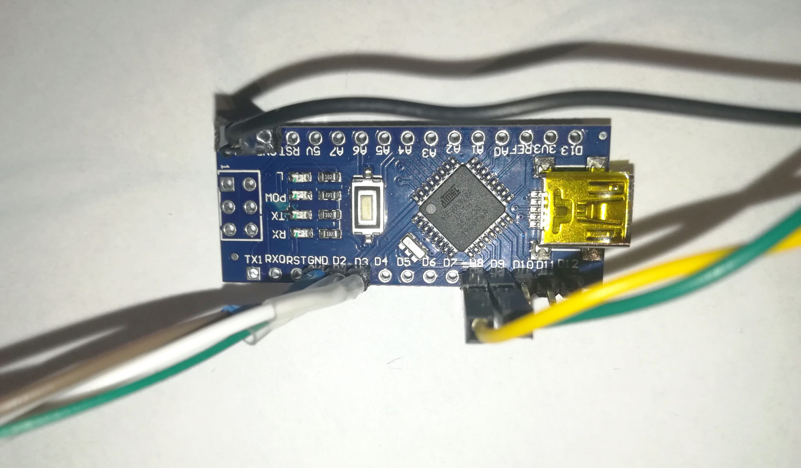
Sulla stazione ricevente ho invece utilizzato un microcontroller Arduino nano. Questa scheda collegata a due canali del ricevitore converte i codici trasmessi in PWM in sequenze LANC che vengono trasmesse alla Z-Cam.
On the receiving station I used an Arduino nano microcontroller instead . This card ,connected to two channels of the receiver, converts the codes transmitted in PWM into LANC sequences which are trasmitted toe Z-Cam.

questa sopra è una immagine che mostra il controller collegato al ricevitore.
this above is an image showing the controller connected to the receiver.
Sotto, il ricevitore (normalmente montato sul gimbal) e il microcontroller.
Below, the receiver (normally mounted on the gimbal) and the microcontroller.

Per gestire da un microcontroller la LANC è purtroppo necessario un piccolo circuito in quanto la LANC è bidirezionale in Trasmissione e ricezione, mentre sul microcontroller un pin può essere usato solo come uscita o come ingresso. Il circuito si compone di pochi componenti, e lo schema elettrico è facilmente scaricabile sul web.
Unfortunately to manage the LANC from a microcontroller a small circuit is necessary as the LANC is bidirectional in transmission and reception, while on the microcontroller a pin can be used only as an output or as an input. The circuit consists of a few components, and the wiring diagram is easily downloadable on the web.
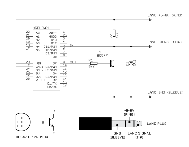
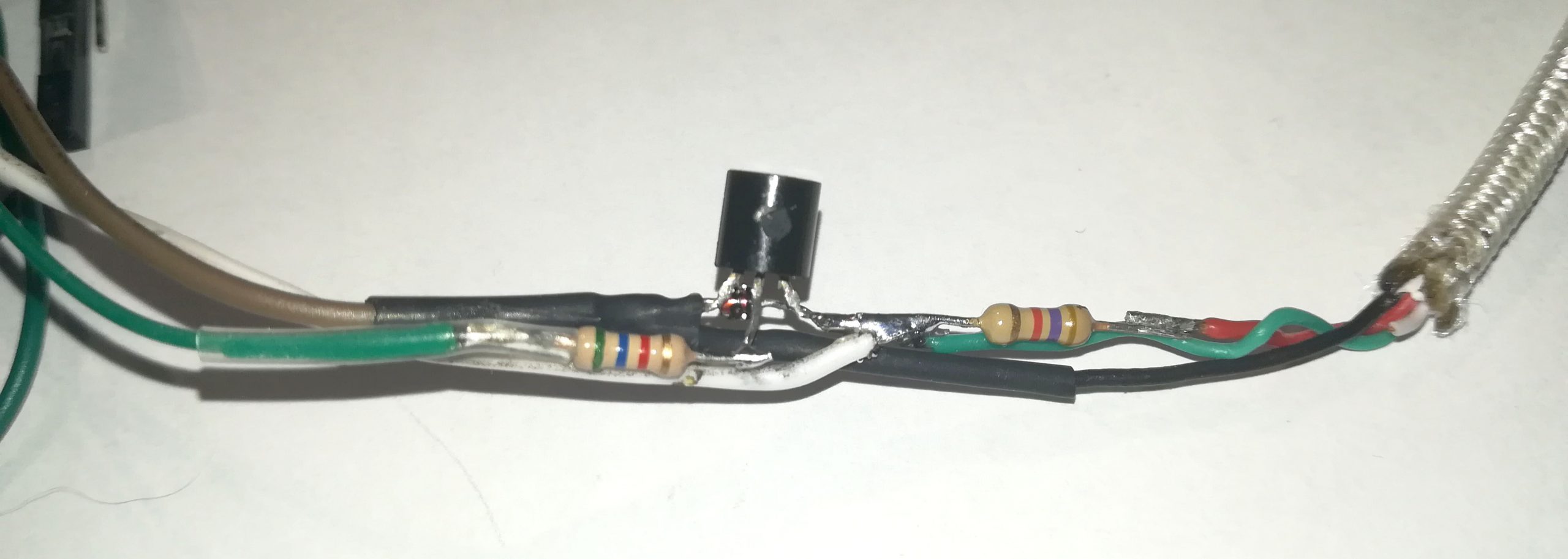
Sopra, a sinistra lo schema elettrico, a destra il prototipo realizzato per i test. Nello schema elettrico, il collegamento tra il LANC +5 V e il VIN di arduino può essere omesso se si decide di alimentare la scheda dal ricevitore anziché dalla camera.
Above, on the left, the wiring diagram, on the right, the prototype made for test. In the wiring diagram, the connection between the LANC +5 V and the Arduino VIN can be omitted if you decide to power the board from the receiver instead of from the LANC Camera
Di seguito, un breve video che mostre la reattività dei comandi e il funzionamento di alcuni di questi:
Below is a short video showing the responsiveness of the controls and the operation of some of them:
Lascia un commento
Devi essere connesso per inviare un commento.